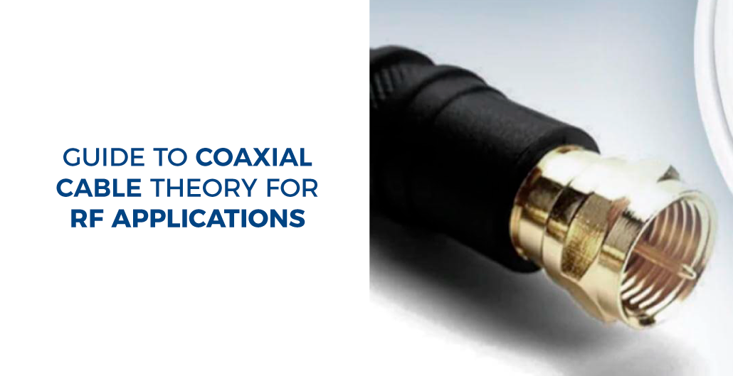
Guide to Coaxial Cable Theory for RF Applications
[fusion_builder_container hundred_percent=»no» equal_height_columns=»no» menu_anchor=»» hide_on_mobile=»small-visibility,medium-visibility,large-visibility» class=»» id=»» background_color=»» background_image=»» background_position=»center center» background_repeat=»no-repeat» fade=»no» background_parallax=»none» parallax_speed=»0.3″ video_mp4=»» video_webm=»» video_ogv=»» video_url=»» video_aspect_ratio=»16:9″ video_loop=»yes» video_mute=»yes» overlay_color=»» video_preview_image=»» border_size=»» border_color=»» border_style=»solid» padding_top=»» padding_bottom=»» padding_left=»» padding_right=»»][fusion_builder_row][fusion_builder_column type=»1_1″ layout=»1_1″ background_position=»left top» background_color=»» border_size=»» border_color=»» border_style=»solid» border_position=»all» spacing=»yes» background_image=»» background_repeat=»no-repeat» padding_top=»» padding_right=»» padding_bottom=»» padding_left=»» margin_top=»0px» margin_bottom=»0px» class=»» id=»» animation_type=»» animation_speed=»0.3″ animation_direction=»left» hide_on_mobile=»small-visibility,medium-visibility,large-visibility» center_content=»no» last=»no» min_height=»» hover_type=»none» link=»»][fusion_text columns=»» column_min_width=»» column_spacing=»» rule_style=»default» rule_size=»» rule_color=»» hide_on_mobile=»small-visibility,medium-visibility,large-visibility» class=»» id=»»]
While we design telecommunications systems, we take into consideration a large number of factors – carrier frequency, fresnel zones, beamwidth, bandwidth, intermodulation, the list goes on.
On the other hand – when we have to start cabling, we really need to analyze the strength and quality signal – that is, the signal that goes into the signal that comes out.

Coaxial Cable Basics
Transmission of DC across a physical medium needs two conductors to create the circuit – the go wire and the return wire.
When it comes to RF transmission, the coaxial cable acts as a kind of transmission line. The go cable takes the form of a center conductor, and the return cable, identified as the outer conductor, consists of an electrical shielding that surrounds the middle conductor.
Since RF is a form of high-frequency alternating current, their wave nature must be evaluated when designing cables.
Unshielded open-wire cables, like those employed in the electricity grid, are suitable transmission lines for purposes in which the frequency bands low enough that power is not lost within the generation of radio waves.
When it comes to RF transmission, unshielded cables will lose power in the generation of radio waves and spurious transmissions induced upon the wire from nearby sources of electrical interference.
The basic concept behind coaxial cables uses the return wire as a shielding mechanism, resulting in the electromagnetic field existing only between the inner and outer conductors.
Centre Conductor
The middle conductor of a coaxial cable is employed to transfer the AC signal and usually consists of either solid copper wire or many strands of twisted copper wire.
Multi-strand center conductors are much more flexible than their solid copper equivalents. Still, they suffer considerably more signal loss per meter of wire (known as attenuation) because of the Proximity Effect.
The diameter, or more importantly, the surface area of the inner conductor, is also important in diminishing Ohmic losses via the Skin Effect.
Dielectric Insulator
The dielectric insulator is utilized to divide the center conductor from the external conductor while at the same time minimizing Ohmic losses resulting from contact with the conductors.
To reduce signal loss, dielectrics frequently consist of aerated elements such as foamed polyethylene, PTFE, or in high power communications supporting structures like spirals, rectangular boxes, and stars are applied to approximate an air dielectric.
Outer Conductor
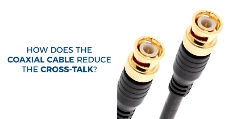
The external conductor of a coaxial cable is held at ground potential and gives electromagnetic shielding – separating the inner electromagnetic signal from external interference and limiting signal power to the confines of the dielectric.
Generally, the external conductor takes the form of a metal wire braiding, and while this provides greater flexibility, gaps between the wires end in RF leakage and interference.
Cable specifications will frequently give a percent braid coverage to provide a comparative metric of the shielding effectiveness.
Outer Jacket
A coaxial cable’s outer jacket doesn’t have any electrical purpose; it simply offers protection from the elements. Typical materials include PVC and polyethylene.
If you would like to receive a quote for any of custom cables or connectors, please do not hesitate to contact us by sending an email to [email protected] or calling in the USA this phone number (682-325-1944)
Jessica Cardona
www.readytogocables.com
[/fusion_text][/fusion_builder_column][/fusion_builder_row][/fusion_builder_container]


